SPI
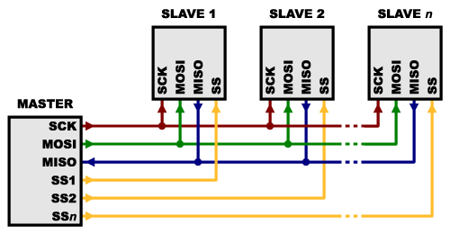
Serial Peripheral Interface (SPI) is an interface bus commonly used to send data between microcontrollers and small peripherals such as shift registers, sensors, and SD cards. It uses separate clock and data lines, along with a select line to choose the device you wish to talk to. Some sensors implement SPI (Serial Peripheral Interface) protocol for data transfer. The SPI protocol basically defines a bus with four wires (four signals) and a common ground. There is one master device controlling the activity on the bus, and one slave device. The slave is active only when one of the signals, Slave Select (SS) enables it. This signal is always provided by the master. There can be more than one slave connected to the SPI bus, but each slave requires its own Slave Select signal, see Fig. 1. The data gets transferred serially bit‐by‐bit. There are basically two signals to carry information, one from master to slave (MOSI, Master Output Slave Input, driven by master), and one for the opposite direction (MISO, Master Input Slave Output, driven by slave). The last signal SCLK (Serial Clock) assures the time synchronization between master and slave, and is always driven by master. There are streamlined versions of the SPI bus using only one signal to transfer data, but the direction of data must be reversed on request; we will not use this kind of data transfer. The speed of data transfer is higher than with I 2 C bus, since the slave is selected using a hardware signal and there is no need to transfer the address of the slave. However, this results in multiple Slave Select signals where more than one slave is connected to the bus. The speed of transfer is typically higher also due to the outputs which should be able to force signals low or high, contrary to the open‐drain outputs used at I 2 C which can force signals low only. The logic levels are defined by the power supply of the devices connected to the SPI bus, and are 3.5V in our case. The actual speed of transmission conforms to the slowest device on the bus, as with I 2 C bus. The SPI protocol is far less strict that the I2C protocol also due to the fact that it was implemented first by several different companies and standardized only later.
What's Wrong
with Serial Ports?
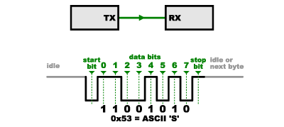
A common serial port, the kind
with TX and RX lines, is called “asynchronous” (not synchronous) because there
is no control over when data is sent or any guarantee that both sides are
running at precisely the same rate. Since computers normally rely on everything
being synchronized to a single “clock” (the main crystal attached to a computer
that drives everything), this can be a problem when two systems with slightly
different clocks try to communicate with each other.
To work around this problem,
asynchronous serial connections add extra start and stop bits to each byte help
the receiver sync up to data as it arrives. Both sides must also agree on the
transmission speed (such as 9600 bits per second) in advance. Slight
differences in the transmission rate aren’t a problem because the receiver
re-syncs at the start of each byte.
Asynchronous serial works just
fine, but has a lot of overhead in both the extra start and stop bits sent with
every byte, and the complex hardware required to send and receive data. And as
you’ve probably noticed in your own projects, if both sides aren’t set to the
same speed, the received data will be garbage. This is because the receiver is
sampling the bits at very specific times (the arrows in the above diagram). If
the receiver is looking at the wrong times, it will see the wrong bits.

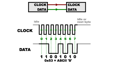
SPI works in a slightly different
manner. It’s a “synchronous” data bus, which means that it uses separate lines
for data and a “clock” that keeps both sides in perfect sync. The clock is an
oscillating signal that tells the receiver exactly when to sample the bits on
the data line. This could be the rising (low to high) or falling (high to low)
edge of the clock signal; the datasheet will specify which one to use. When the
receiver detects that edge, it will immediately look at the data line to read
the next bit (see the arrows in the below diagram). Because the clock is sent
along with the data, specifying the speed isn’t important, although devices
will have a top speed at which they can operate (We’ll discuss choosing the
proper clock edge and speed in a bit).
One reason that SPI is so popular
is that the receiving hardware can be a simple shift register. This is a much simpler (and
cheaper!) piece of hardware than the full-up UART (Universal Asynchronous
Receiver / Transmitter) that asynchronous serial requires.

Multiple slaves
There are two ways of connecting
multiple slaves to an SPI bus:
1. In general,
each slave will need a separate SS line. To talk to a particular slave, you’ll
make that slave’s SS line low and keep the rest of them high (you don’t want
two slaves activated at the same time, or they may both try to talk on the same
MISO line resulting in garbled data). Lots of slaves will require lots of SS
lines; if you’re running low on outputs, there are binary decoder chips that can
multiply your SS outputs.


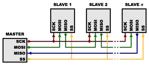
Note that, for this layout, data
overflows from one slave to the next, so to send data to any one slave, you’ll need to transmit
enough data to reach all of them. Also,
keep in mind that the first piece of data
you transmit will end up in thelast slave.
This type of layout is typically
used in output-only situations, such as driving LEDs where you don’t need to
receive any data back. In these cases you can leave the master’s MISO line
disconnected. However, if data does need to be returned to the master, you can
do this by closing the daisy-chain loop (blue wire in the above diagram). Note
that if you do this, the return data from slave 1 will need to pass through all the slaves before getting back to
the master, so be sure to send enough receive commands to get the data you
need.
Implementaton
of SPI
Many microcontrollers have
built-in SPI peripherals that handle all the details of sending and receiving
data, and can do so at very high speeds. The SPI protocol is also simple enough
that you (yes, you!) can write your own routines to manipulate the I/O lines in
the proper sequence to transfer data. (A good example is on the Wikipedia SPI page.)
If you’re using an Arduino, there
are two ways you can communicate with SPI devices:
1. You can use the shiftIn() and shiftOut() commands. These
are software-based commands that will work on any group of pins, but will be
somewhat slow.
2. Or you can use
the SPI Library, which takes
advantage of the SPI hardware built into the microcontroller. This is vastly
faster than the above commands, but it will only work on certain pins.
You will need to select some
options when setting up your interface. These options must match those of the
device you’re talking to; check the device’s datasheet to see what it requires.
- The interface can send data with the
most-significant bit (MSB) first, or least-significant bit (LSB) first. In
the Arduino SPI library, this is controlled by the setBitOrder() function.
- The slave will read the data on either the
rising edge or the falling edge of the clock pulse. Additionally, the
clock can be considered “idle” when it is high or low. In the Arduino SPI
library, both of these options are controlled by the setDataMode() function.
- SPI can operate at extremely high speeds
(millions of bytes per second), which may be too fast for some devices. To
accommodate such devices, you can adjust the data rate. In the Arduino SPI
library, the speed is set by thesetClockDivider() function, which divides
the master clock (16MHz on most Arduinos) down to a frequency between 8MHz
(/2) and 125kHz (/128).
- If you’re using the SPI Library, you must
use the provided SCK, MOSI and MISO pins, as the hardware is hardwired to
those pins. There is also a dedicated SS pin that you can use (which must,
at least, be set to an output in order for the SPI hardware to function),
but note that you can use any other available output pin(s) for SS to your
slave device(s) as well.
- On older Arduinos, you’ll need to control
the SS pin(s) yourself, making one of them low before your data transfer
and high afterward. Newer Arduinos such as the Due can control each SS pin
automatically as part of the data transfer; see the Due SPI documentation page for more information.
Any examples
of an SPI based protocol with a checksum?
1. An example of communication between a microcontroller and an
accelerometer sensor using the SPI interface will be demonstrated in this
example.
2. I have an application in which I need to communicate
via SPI with an FPGA. Both the FPGA and microcontroller are in our control,
and so I have the flexibility to define the protocol as I see fit.
Is this workable? Are there any better examples out
there?
EDIT1: Some clarification on requirements:
·
The microcontroller is to read and write small blocks
of data to/from the FPGA.
·
The FPGA will support read/write operations to
registers.
·
The registers can be many bytes deep (like a fifo) or
autoincrementing (next read or write byte comes from the next register).
·
I would like the operation including the checksum / ack
to occur in a single transmission.
·
I would like this have a low overhead, some operations
will be fetching or posting 5-10 bytes. The largest could be 127 or 64.
|
- RISHYAB KOUL
No comments:
Post a Comment